DaveT
-
Posts
5087 -
Joined
-
Last visited
-
Days Won
87
Content Type
Profiles
Forums
Gallery
Store
Everything posted by DaveT
-
The ones I've resealed, the seal face is pretty close to flush with the housing. I do know that some seals are made in different thicknesses, but it's hard to measure that now...
-
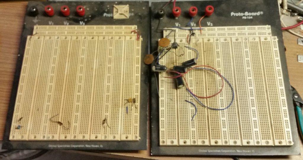
It looks like the CPU is in mode 1, if my thinking about the capacitors is correct. But this doesn't match the table 3 in the CPU data sheet, because the address and data are multiplexed from what I have traced so far. According to the wiring traced so far, it's mode 0,2,4, or 6. I can capture the state of those pins once we have determined all the GND & power wiring and I can power the thing up. Getting the logic analyzer close to the car is not very practical.
-
 If the engine isn't leaking don't touch the gaskets. I don't use anything but oem or Fel Pro for heads, and the others. As above, have space or boxes whatever to put parts in to keep related things together. Non interference refers to the arrangement of the internals. As in, if the timing belt broke, would pistons hit valves. Interference engines ,if the timing belt breaks, pistons hit valves and is very expensive to fix. Non interference, just replace the belt and idlers, and drive.
 -
Complete GL to BRAT Swap
DaveT replied to Divisible_By_0's topic in Old Gen.: 80's GL/DL/XT/Loyales...
Yes, the difference between push rod and overhead cam. A lot wider. -
In a general way for now, the ecu knows the rpm, airflow, throttle position, and pulse from the distributor, and fires the coil. Some combo of math and look up table would adjust the delay = advance / retard.
-
87 dl wagon front defroster wont work.
DaveT replied to brutee's topic in Old Gen.: 80's GL/DL/XT/Loyales...
The buttons are vacuum valves. Vacuum actuators move the doors to rout the air. A lot easier to see when the heater box is out of the car, which unfortunately involves removing the dash. First thing is to see if you can get eyes on those, see if they move. -
What the heck did I just do to my Brakes?
DaveT replied to Sapper 157's topic in Old Gen.: 80's GL/DL/XT/Loyales...
The mounting bolts might snap off. Anti seize the new ones. If you haven't used antisieze before, be aware that it lubes the bolts, and be careful of over toqueing. You're welcome. -
What the heck did I just do to my Brakes?
DaveT replied to Sapper 157's topic in Old Gen.: 80's GL/DL/XT/Loyales...
Excellent. Yeah, those bleeder do that. Lots of anti seize compound, and the rubber cap helps for next time. -
Bolt sizes for Trans to EA82 Engine?
DaveT replied to BRM's topic in Old Gen.: 80's GL/DL/XT/Loyales...
yes, that characteristic of typical replacement bolts annoys me also. It's the different convention used between Japan made metric and Europe made metric. -
I have also found that pins 9 & 10 [2 of the 3 mode select pins] on the CPU have 100nF capacitors to GND. Reset Has a 10nF. Those 2 will be low longer than reset. Not sure if it would be long enough for it to read them as low at power up, but maybe?
-
The RAM and EPROM - Address low byte and data are wired parallel. Address high byte also, except the EPROM has one more bit than the RAM. CPU pin 37 wires to IC6 74LS373 pin 8 D4 This is data bit 0. The Q from the latch IC6 is pin 9 This goes to the Address line A0 This makes sense, for a multiplexed address & data bus. It is like the micromint processor systems I've wired up. So port P3 [0-7] on the CPU is multiplexed Address low byte and data.
-
There should be room. Yes, this isn't a 1 night project. More a bit late tonight...
-
Complete GL to BRAT Swap
DaveT replied to Divisible_By_0's topic in Old Gen.: 80's GL/DL/XT/Loyales...
80 to 89, I'm kind of guessing, because i don't specifically know brats, but i think you'll need the harness and all the dash instruments etc. As far as I know, an 80 would be carburetor, and an 89 spfi. The mechanical stuff, others will know, because of other partial swaps I've seen. -
Yeah, it had its original exhaust also. I put my all stainless one on it. It weighs less and easier to move if needed for other work.
-
Probably weather related. I got a car from California 2 years ago. Just replaced a ball joint a week or 2 ago. Everything just unscrewed and dissasembled. 23 year old car and the bolt still have the yellow zinc anodize on them. All coated with anti seize now, of course.
-
rpm see saw
DaveT replied to MrB's topic in 1990 to Present Legacy, Impreza, Outback, Forester, Baja, WRX&WrxSTI, SVX
Probably not o2 sensor. Maybe CTS. Maybe an intermittent wire or connection. -
Ok, I'll check it those. I borrowed a better set of probes from work. Also start on removing the CPU.
-
Bolt sizes for Trans to EA82 Engine?
DaveT replied to BRM's topic in Old Gen.: 80's GL/DL/XT/Loyales...
From memory.... pretty sure they are 14mm hex heads. 10mm diameter. 1.25mm pitch. Lower nut on the starter was 17mm hex iirc. Other nuts were washer face or used with washers and split locks. -
ECU rom 1 asm list.txt dis assembly listing of EPROM starting at address 0000 which may be wrong.
-
http://www.ic37.com/HD46520P-p.htm This site seems to list the HD46520 - maybe old stock suppliers? Couldn't find data sheets. HD46508 may be similar, but pin 2 is not an output, so it can't be drop in equivalent.
-
The LED that blinks the trouble codes: Driven by a 2sc458K Hitachi transistor. E is grounded via a BLK / YEL wire in connector F107 that goes to the engine block GND. The Base is driven by IC2 Pin2 [HD46520P]
-
Few questions about the BRAT; value, problems, ect
DaveT replied to Paperscale's topic in Old Gen.: 80's GL/DL/XT/Loyales...
Bubbled paint rust is worse than you might think. It's coming through from behind. You will be doing yourself a big favor to find a Factory Service Manual for whatever model & year you end up buying. All those details of what's missing or just an option the car doesn't have are in there. Of course, no harm in asking here either, it just helps a lot to have the info on hand. -
The CPU crystal is marked: 4000 SAWA-1 KSS50 I'll be able to measure the frequency once we have figured out power connections.
-
I've been using that. They also have a copper version now, I have been using. Not long enough to have long term idea yet. I've also used synthetic wheel bearing grease / GL2 and that stays around for a long time too.
-
Yes, I suspected IC3 is RAM also. Just by the size and location. Yes, good idea to compile a table of the parts with data sheet links. I have downloaded the ones I've found, and the ones posted so far. Are there any online ocr webpages?