


jonathan909
-
Posts
856 -
Joined
-
Last visited
-
Days Won
26
Content Type
Profiles
Forums
Gallery
Store
Everything posted by jonathan909
-
 Disclaimer: I know nothing about ATs; the extent of my experience is replacing the 4EAT in my '99 Forester. It was suffering from a neck-snapping 4-3 downshift under power - if you stepped on it for passing, to get power on a hill, etc., it felt like you were being rear-ended at speed. No codes. Xmission repair shop estimated $2400 (a nonstarter). Found a matching transmission in a junkyard car; it had body damage (implying it was mechanically sound when taken off the road), so I took a flyer and spent $130 and an afternoon dropping it. When I bolted it up it worked perfectly. Having said that, if I were in your situation I'd get my butt to a (preferably self-serve) wrecking yard and pull a valve body. Around here they charge $50 for them.
 -
Oh, I get it. You're feeding it a pulse train slower than normal to make the ECM think the car's groundspeed is lower than it is. I can't speculate on what other implications that might have. Any idea what normal is, in Hz/mph or something? What do you think your top end speed should be? [Edit] That's interesting - the xmission's speed sensor output doesn't go straight to the ECM. It gets fed into the speedometer circuit (in the gauge cluster) which in turn feeds the ECM VSS input. That could either just be a wiring "convenience", or the speedo circuit is conditioning that signal somehow. Seems to me the easiest approach to debugging this would be to unplug your VSS hack and put a gauge cluster in to see if it behaves differently.
-
I really don't know $h!t about $h!t, but I'm kind of curious about this. Assuming that by "We built a circuit to simulate the 5 volt signal on pin 83 to the ECM for the VSS." you mean you built an oscillator that feeds a pulse train to the VSS input, why would you go to all that trouble instead of just connecting the transmission's speed sensor output to it as usual? (I was also briefly confused by this, as "VSS" has a totally different meaning in my world - it's a power supply rail, usually ground.) And is p.81 grounded to tell the ECM that it's connected to a 5MT?
-
Here's the thing: That's what I found while disassembling the strut - that I was able to get a (cheap) offset onto the stock 17mm nut. However, no way no how was there enough room to get one onto the 21mm nut that the aftermarket shocks came with. That's why I'm getting a pass-through set.
-
To be fair, I've only replaced one pump (out of the six cars I've owned - not thousands!), and it was in the '02 Forester that I rescued from a country junkyard after it'd been sitting there for nine years. Fools hadn't drained the tank when they parked it, so after I replaced the motor the fuel pump was the next step. It was seized solid, there was corrosion all over the bracket, and the rubber mount had dissolved into a sticky gob resembling half a dozen packages of well-chewed Black Cat gum.
-
Why, you're lucky. Around here, we walk uphill both ways. (For anyone wondering - and those who weren't - Monty Python were ripping off Stephen Leacock when they did that bit - Cleese admitted it.)
-
Well, or another carrier (USPS?), or leave a note saying "sorry for the blocked driveway, please leave package in car", or deliver to a neighbor, or...
-
Good. With the right tools, though, you won't even have to do that.
-
For good prices on parts, I haven't found any better than Rock Auto (other than a wrecker), though others here may differ. The hoses you just have to fight with. That it's turning is a good start; beyond that, sometimes slipping a really skinny little screwdriver between the hose and the pipe will help loosen it. And if you can push on the end of the hose rather than pulling on it, it'll tend to expand and slide off rather than squeeze tighter. I suppose squirting a little lube like WD-40 between the hose and pipe may help as well, without causing any problems.
-
My pleasure entirely. Sounds like you've got it well in hand. I've only messed with these things in 99-02, so I don't know which style of pump the 95 has. So are you now stuck at home, bingeing a TV series, until the UPS man shows up with a package from Rock? Or do you have some local support that might give you a lift to a local parts source?
-
That's precisely what I'd take it to mean. Sounds like it's time to pull that cover and get the old one out and confirm it's dead. What's your plan for getting a replacement?
-
Hubba-hubba! Zackly what you need.
-
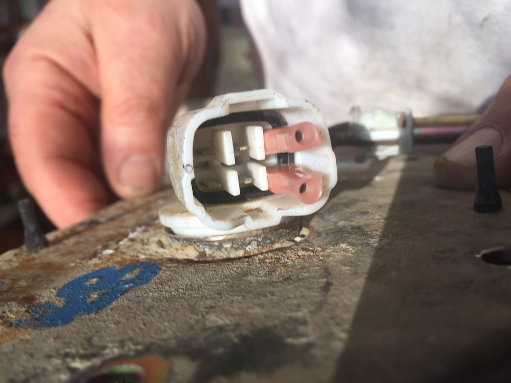
I empathize - I'm way out in the country too, but with the advantages of a ridiculous stockpile of stuff to work with and (usually) an extra car to get about in for things like this. If you're CAREFUL, you can run a quick test (that's all you need right now) with that alligator clip on the lower pin (as shown in your photo) and just a piece of wire for the upper. If the wire is something like AWG 16 or heavier, cut the end flush. The insulation will give you reasonable protection from shorting against the clip, but the exposed end will still make contact with the pin. Remember, you only have to make contact for a few seconds so you can hear the pump run (or not), so you don't have to be elaborate about this. As for anything under the dash, yeah, that's how it is. I'm sure it appears in one of Dante's circles of hell.
-
I have the wagon too, and I still wouldn't chase wires. There's no way you're going to jam two alligator clips of that size in there without shorting them together, so you should definitely snag a couple of the small quick-disconnect crimp connectors. (Photo credit: My daughter Becky)
-
Sorry, I can't help on the rumoured-wire front - I'd just find a way to connect to those (male) pins. If you can lay your hands on some small (e.g. 1/8") female "quick disconnect" crimp lugs, they may push onto the pump pins. Otherwise, I'd disconnect those three hoses and pull the cover (it's only eight nuts, so you'll have it off in a minute) and lift out the whole fuel pump and sending unit assembly. Then it'll be easier to test "on the bench". Personally, I'd rather do that than start pulling seats and chasing wires.
-
Looks like the original nut was a predictable 17mm, while the replacements are an annoying 21mm. Also appears I'll use this as an excuse to buy a pass-through socket set. (For the canucks in the audience, Princess Auto has a decent-looking Channellock set on now for $50 that goes up to 22mm.)
-
The pass-through socket is definitely the way to go - I just did a set of four in August. IIrc, the nut sizes varied between those that were on the car (presumably factory) and the aftermarket replacements I got from Rock. I think I still have the old ones in the scrap bin and can check a little later.
-
Stands to reason that it'd be carbon, but maybe in some weird annealed state. Not being a carbon chemist, I really can't speculate further, but I remain curious.
-
No - the valves don't have to come out to pull the shims, but I removed/reinstalled the one I had to grind the stem on. I suppose one could grind it in situ, but I don't think I'd try that myself (for the obvious reasons). But lacking Subaru's (expensive) fancy-shmancy tool, the cam has to come out for each shim change - or at least be loosened off to get the clearance to slide the shim out. Shim grinding strikes me as counterintuitive. Much more material to be removed than just grinding the valve stem, and unless you've got precision machine tools, impossible to grind true.
-
New question: My exhaust valves (and for some reason, it's a lot worse on one head than the other) have a thick white deposit on their faces that's really hard - the wire wheel barely touched it, and I had to take most of it off using one of those little sintered Dremel burrs. What is it, and why is it there?
-
Be looking forward to a progress report. Also, please note my edits in paragraph 2 that aren't in your reply.
-
Okay, go to p.44 of the PDF, titled "13. ENGINE ELECTRICAL SYSTEM LHD model" (it says p.51 at the bottom of the page). There's your fuel pump on the left side of the drawing. Print this page - people who try to debug stuff like this on their phones drive me nuts. As you can see, the connector at the tank is R58. Look at the bottom of the page and they describe it. Pins 1 and 4 are the ones you're interested in, and the drawing says that the positive side (which goes to the relay) is LY (Blue + Yellow) and negative (ground) is B for Black, respectively. Don't ask me why they chose L for Blue; I think it's stupid too. Confirm that those are the wires that correspond to the correct pins. Unplug the connector. Connect pin 1 to the positive (+) side of your battery and pin 4 to the negative (-), and you should hear your pump run. There may be a little spark when you connect it up; as long as the pump is running, don't worry about that. But if you get a spark and the pump doesn't run, the motor may be seized/shorted and you'll start burning wiring if you leave it connected, so unhook it without delay. Be careful. If you short the wires together - even with a battery you don't think is very good - you're going to get some or all of: sparks, heat, melted insulation, burnt fingers, and damaged connector pins that will add to your repair job. I do electronic stuff, so I've got lots of little grabby clippy things around; if I didn't, I'd go to the junkyard and snip off one of those connectors with as much wire as I could manage to give me a "pigtail" connector to do these tests with. How you do it is up to you based on what you have around, how much of a hurry you're in, how close the nearest wrecker is, etc. Follow all that?
-
Did you get the wiring diagram PDF I linked to in my previous post? Fwiw, my '95 rustbucket has 450K km on it - it got a new motor+gearbox a couple of years ago, but no problems to date in the fuel delivery department.
-
Don't worry, you're not going to need any electrical theory - or a mechanic. But you will need the diagram, because that's where you're going to see which pins on the fuel tank connector you have to connect power to. Assuming it's like the later ones I'm familiar with (I've never had to mess with the fuel assembly in my '95), there's a single connector that supplies power to the pump and sends the fuel level information back to the dash gauge, and you can mess things up if you power the wrong pins. Next, what is your power supply? Are you just running wires back from the battery, or do you have something else that can provide 12V at the back of the car for this test? [Edit] Here - go get this: http://jdmfsm.info/Auto/Japan/Subaru/Legacy_Outback/1995/1995 Legacy Wiring Diagrams.pdf and I'll walk you through it.

