Rampage
Members-
Posts
683 -
Joined
-
Last visited
-
Days Won
25
Content Type
Profiles
Forums
Gallery
Store
Everything posted by Rampage
-
Well, you have done a super good job so far, because it runs. I hope you find the missing link. I've got a lot of work to do tomorrow, swap two front axels, charge the A/C in the van, put a window air conditioner in the house and finish up a laptop. Got to go.
-
The CEL bulb should be the same number bulb as in your 92. If it draws too much current the ECU transistor may not be able to make it light. Some times they use an Emitter resistor to ground to protect the transistor from a shorted bulb. If the bulb is correct, what it sounds like, is there is an input to the ECU missing or incorrect causing the ECU to not switch the CEL on with the key. In other words the ECU does not know you turned the key on, or it thinks the engine is running and does not switch the CEL light on.
-
I know someone else can answer that question for sure, but I think they are different.
-
What I've run into with a lot of electronic units, not just automotive, over the years is, any OE manufacturer will have parts (chips and transistors) labeled with "house" part numbers on them, so there is no public cross reference for those part numbers. In the past, if I had a schematic of the unit, or could draw the circuit on paper I could come up with a replacement part that would work. But, that was like 15-20 years ago. Probably your only options are to try your ECU in another original car that it came from and see if it behaves like normal, or recheck your wiring (again) and try your other ECU.
-
100 % correct. Just a momentary direct contact with 12 volts would burn out the transistor.
-
Possible. But not sure. I can not find internal info on the ECU. In electronic circuits, they sometimes use a pull up resistor on the collector of a NPN transistor and it will show voltage if the transistor in not switched on and not connected to a load circuit (bulb). A lot of the circuitry inside the ECU runs on 5 volts from voltage regulators built into the unit. When the collector is connected to a circuit like the CEL light you would normally see about the same voltage on both sides of the bulb. If they are using the 5 volts on the pullup resistor instead of 12 volts then you would see 5 volts with an open circuit. Newer ECU's monitor that voltage and if it is not higher than 5 volts it will say hey you've got a burned out CEL bulb. In case you don't know, a simple transistor has 3 terminals, Emitter, Base and Collector. With an NPN transistor the Emitter is grounded. When a little voltage like 3 tenths of a volt is applied to the Base, the Collector will pass current to the Emitter, effectively grounding the Collector. Like turning on a switch.
-
They have metal clips that hold them onto the tank. No. They are metal and bent to match the shape of the tank. Our cars being AWD have a second round access cover opposite the fuel pump cover. I fished a solid 12ga copper wire between the two access holes and wrapped and taped it to both new hoses and used it to pull them through from the fuel pump side, then over and down the side of the tank to the metal pipes that come through the floor.
-
The fuel lines up and over the fuel tank are metal. Because of a leak in the return line, I replaced both, the supply and return with fuel injection hose on our 95 Legacy RHD wagon. I did one at a time. I used 100 PSI fuel injection hose. On the 90's Subaru, the max fuel pump pressure on some pumps can be around 60 - 85 PSI, but it runs at less than half of that pressure around 26 - 38 PSI. The FSM will give you specs on your pump. The 100 PSI hose will be fine even it the fuel filter gets completely clogged. For the power steering pump, check the pipe connection to the pump. They used different types of connections through the 90s. I run Chevy Cavalier wheels on our 95. They have a slightly larger center hole than the Subaru wheel. You need all 4 because they move the tire 1" outward. I am sure there are others that will fit, but I never checked it out.
-
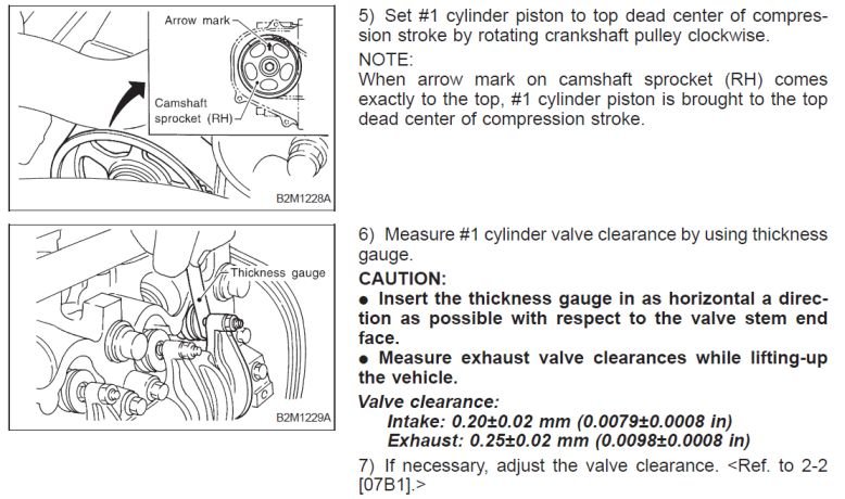
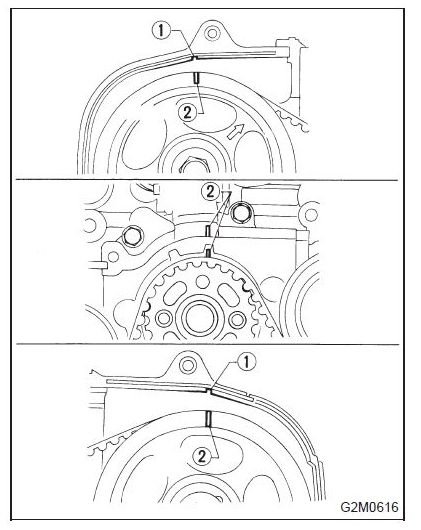
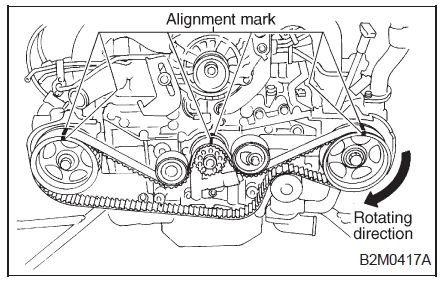
I never looked into it, but they want the timing belt installed in that position. The first time I did the timing belt I noticed that the (passenger side) Right cam sprocket turns free (no valves open) and the Left cam has valves wide open (top of the lobe). I think it may be, so that the cams will stay put while installing the belt. Then they want it turned to adjust valve lash.
-
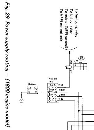
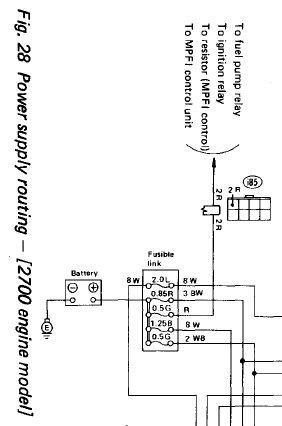
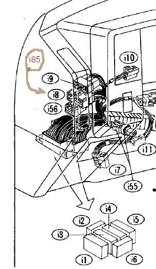
I am using the FSM for an 88 XT. Hope your 89 is similar. http://jdmfsm.info/Auto/Japan/Subaru/--Old Models--/ For the radio- Check fuse #5 - 15amp. It supplies constant 12 volts to the solid white wire on the radio connector. It goes through 3 connectors to get to the radio plug. It also powers these circuits Auto antenna, Horn, Diode box, Height control unit, Hazard, Trunk room light, Radio, Trip Computer, Clock, Automatic seat belt unit, Key warning switch. Green Fusible Link- see pics. Check voltage on both sides of red wire on connector i85(aka i8). Left side of dash. The wiring diagram shows a connector number, then you go to a chart to get the location number. Weird.
-
Pull all 4 spark plugs and keep them in order. See if they have a four digit number stamped on the hex. If not then they are FAKE NGK plugs. Go to Google.com and type in Fake NGK spark plugs. If they are ok, swap 1 and 3 then 2 and 4. If you still get 3 and 4 misfire check the fuel injectors. The FSM says 5 to 20 Ohms. That seems like a wide range to me, so unplug the connectors and compare all 4. See if 3 and 4 are different than 1 and 2.
-
What is the voltage "there" when you turn the key on and try to start?
-
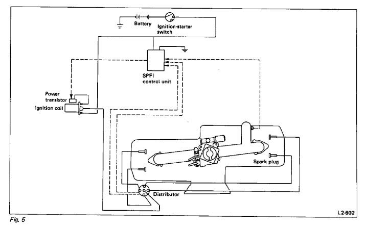
Not normal. Electronic ignition uses pulses from the distributer or SPFI Module to fire the coil. If the engine is not turning, no pulses, no current through the coil, no heat. There should be battery voltage on the + and - of the coil. The coil bracket should have a power transistor (ignitor) mounted on it? If so, it is probably shorted. You can unplug it and test it with an OHM Meter. Put the meter on the diode symbol if it has one, otherwise use the lowest OHM setting. The transistor has three terminals one is ground. Put the black probe on ground. You might see 75 on one pin, If you find a very low reading on the other terminal, it is toast. If you get no short on the transistor, the only other thing that could turn the transistor on would be a voltage leak that should not be there from the SPFI module. The diagram is for an 89. The transistor works like a switch. An input pulse turns it on and connects the coil negative to ground and when the pulse turns off, the coil will produce a spark.
-
You should check the coil + and - to ground with the volt meter. If you have a test light, hook the clip to ground and hold the probe tip on the coil negative and crank the engine. Does the light flicker?
-
You have changed the coil and it is still dropping spark on 1 and 2 so check the inputs to the coil and where they come from. Uncover the ECM and identify the two wires and pins 18 and 19 on connector B137 so you are ready to test them. With the key off, remove connector B137 from the ECM and look for corrosion on pins 18 and 19. I have not seen corrosion on those pins, but anything is possible. Replace the connector. Use a volt meter and compare the voltage on Pins 1 and 4 of the coil plug (the two outside pins) when the engine is running normal and again when it is misfiring. When misfiring, there will be a difference in voltage on one of those pins. When it is misfiring check the voltage at the ECM connector B137 Pins 18 and 19. If the voltages on the ECM pins read the same as on the coil, then the ECM is at fault. If they are different then the problem is the wire between the two connectors. I don't know if the difference in voltage will be a high or low, since I don't know if they use NPN or PNP transistors in the coil and ECM.

