Rampage
Members-
Posts
683 -
Joined
-
Last visited
-
Days Won
25
Content Type
Profiles
Forums
Gallery
Store
Everything posted by Rampage
-
Right, it will. That is because the coil is made of wire. Your picture showed the wires NOT connected to the coil, otherwise I would have said disconnect them.
- 56 replies
-
- 1
-

-
- subaru loyale
- help
-
(and 3 more)
Tagged with:
-
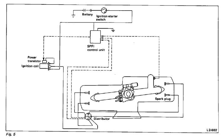
When you turn the ignition switch key to ON, one of the two eyelets will show 12 volts and that one goes to the coil positive terminal. The other eyelet goes to the coil negative terminal. That wire actually goes to the transistor. The transistor should be grounded through the coil bracket. The third connection for the transistor is the wire that comes from the SPFI module that carries the pulses to make the transistor switch on and off to produce spark from the coil.
- 56 replies
-
- 1
-

-
- subaru loyale
- help
-
(and 3 more)
Tagged with:
-
- 56 replies
-
- subaru loyale
- help
-
(and 3 more)
Tagged with:
-
That reminds me, I found the plug inside the tank for that connector fried about a year ago on our 95 RHD. The Denso pumps have a pigtail with a plug on each end, one for the pump and one for that connector. My wife was on her mail route she called and said she could not hear the fuel pump run. I grabbed my spare pump and a box of other stuff and tools and we swapped cars. Lucky I had some wire with. I wire nutted onto the pump wire inside the tank and hooked to a wire with a cigar lighter plug. Drove home and replaced it.
-
The two eyelets for the coil. When you turn the key ON, one of them will go to 12v. That one goes to the coil positive + and the other one is coil negative. Don't know about the other one.
- 56 replies
-
- subaru loyale
- help
-
(and 3 more)
Tagged with:
-
92 Loyale odd light issue
Rampage replied to Ionstorm66's topic in Old Gen.: 80's GL/DL/XT/Loyales...
Glad to know you fixed it. D a r n switches, maybe someone spilled their beer on it on a bumpy road. Our 95 has 472k miles and that switch still works. -
Ea82 ignition switches short
Rampage replied to Olyroller83GL's topic in Old Gen.: 80's GL/DL/XT/Loyales...
Yes one wire is always hot. 1 for ACC, 1 for IGN, 1 for START. If the insulation on the whole length of the wire from the switch to the connector is melting it makes me wonder if it is the proper gauge wire. Usually it only melts several inches from a corroded connection. As naru2 said, eliminate the connector. Inside the vehicle you can use wire nuts, but soldering is best. Also, bypassing IGN Switch Start with a push button or relay will relieve that load on the IGN switch. I have done in on our 95 and 97 Legacy. -
The following is from the attached text file, something I found years ago in a Subaru 4EAT Training manual that I borrowed from a friend. If shift solenoids #1 or #2 malfunction, the TCU deactivates the other. This results in either 3rd gear or Reverse (when selected). 4EAT Fail Safe Components and Failure Results.txt
-
92 Loyale odd light issue
Rampage replied to Ionstorm66's topic in Old Gen.: 80's GL/DL/XT/Loyales...
Looking closer at the wiring diagram I can see that when the Parking Switch is ON the parking lights only will light, NO Dash Lights. When the Parking Switch is OFF it makes a connection so that when the Headlight Switch is turned ON to parking lights, the parking lights and the Dash lights will light. Same for headlights. So, it looks like the Parking Switch might be good and the Relay may be bad. I think it is the Relay because it is controlled by the headlight switch and turns on the parking lights, then that power goes through the Parking Switch (OFF) to light the Dash and other lights. The relay is listed as Tail & Illumination Relay. -
92 Loyale odd light issue
Rampage replied to Ionstorm66's topic in Old Gen.: 80's GL/DL/XT/Loyales...
Check Fuse # 23 - 20amp and Fuse # 9 - 10amp. Also check Tail & Illumination Relay. The wiring diagram does not show the location of these. If those parts are ok, then it will be the switch or a poor connection, because that switch routes power in both positions ON and OFF. -
No, you cannot bypass it. The transistor in the control unit will not handle the current of the coil. How many wires on it and is it grounded to the coil bracket? To act as a transistor power switch for the coil it would have a signal input, a ground and an output to the coil. What it does is, take the high current load of the coil away from the SPFI Control Unit, or ECU or ECM in later models. It is the same process as produced by using a relay. A small current can control a large current. Transistors can switch on and off really fast like millions of times per second. I was looking at wiring diagrams and you may be able to wire in a later model Igniter in place of the Power Transistor. The Igniter is basically the same thing, only it is built to run two coils in a pack instead of one coil. I looked at the 95 and 97 Legacy because we have them. Remove one of the two wires on the coil terminals. With the key on, there should be battery voltage on one of the two wires. The one that does not show voltage goes to the Power Transistor. Remember which one that is. To test the coil hook up a spark plug wire to the coil and a spark plug. Ground the spark plug body somewhere on the engine. Turn the key on and take a wire grounded on one end and tap the other end on the coil terminal that goes to the Transistor. Do not hold it on the terminal, just tap it. There should be a spark when you remove the wire from the terminal. When the wire touches the terminal the coil generates a magnetic field. When the wire is removed that magnetic field collapses and produces a spark. The input wire to the Power Transistor should show a low voltage pulse on a volt meter when cranking the engine. What I don't know is the impedance (electrical resistance at certain frequencies) of the old coil compared to the newer coils. There will be a capacitor (or condenser) either external or built into the Power Transistor. That capacitor is used to complete the coil circuit to ground when the transistor switches off and the magnetic field collapses and produces current in the high voltage winding of the ignition coil. If you decide to try wiring in the Igniter, the following is how to wire it. Go to a yard and get the Igniter and plug. Cut the wire harness long, so you have wires to work with. You can trim off the wires later. It is mounted at the center of the firewall on the bracket for the support that goes to the top of the bellhousing. Remove the Power Transistor. On the Igniter connector there are 6 terminals but only 5 Pins are used. Pin 3 has a black wire, so you can easily decode the other pins. Wire colors. First letter is wire color. Second letter is the stripe color. Black, Green, Lavender, Red, Yellow, Violet. Pin # and Wire color. Pins 1 YL & 2 YV - connect the wires together and they go to the signal Input wire that originally went to the Power Transistor. Pins 5 L & 6 RG - connect the wires together and they go to the coil terminal. Pin 3 B - goes to a GOOD ground. I wish I had something to try this on, but I don't. Connecting the wires together hooks the two transistors in parallel so the coil current is divided between them. What I do not know is what the combined input load will put on the computer signal. It depends on the resistor circuit for the transistors built into the Igniter. We may have to break it down to just one circuit. Let us know if you try it and how it works out.
- 56 replies
-
- 1
-

-
- subaru loyale
- help
-
(and 3 more)
Tagged with:
-
85 Brat exhaust, resonator needed
Rampage replied to mkoch's topic in Old Gen.: 80's GL/DL/XT/Loyales...
A later model part from a junk yard might be the same size, but I don't know. It should be the same length and diameter in order to do the same job. If you need one and can't find it, make one. The resonator is just an "empty" chamber that helps to remove the high frequency sounds from the exhaust before going to the muffler. If you use a pipe to bypass it, you may not like the sound of the exhaust, or maybe you will. Measure the body length and diameter of your resonator. Get a piece of exhaust pipe the same diameter and cut to length. Most auto parts stores have on hand 18" lengths of exhaust pipe at least up to 3" dia. and adapters to bring it down to your Brats exhaust pipe size. Install pipe adapters on each end of the big pipe with the ID of the small ends of the adaptors to match the OD size of your exhaust so they will go over the out side of the exhaust pipe. I would have the unit welded for less chance of leaks. Some guys spray paint the welds with high temp paint to help control rust. The odor will go away in a short time. Cut the old resonator off, use two clamps and your done. -
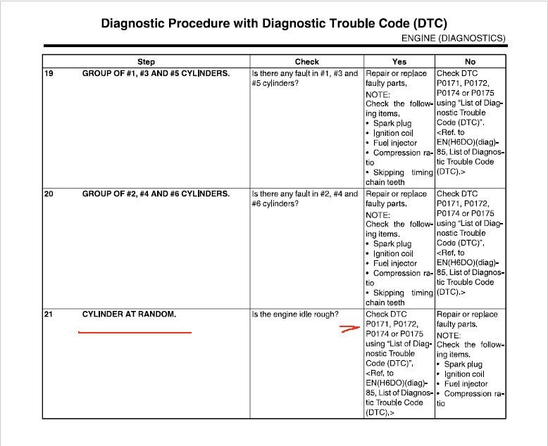
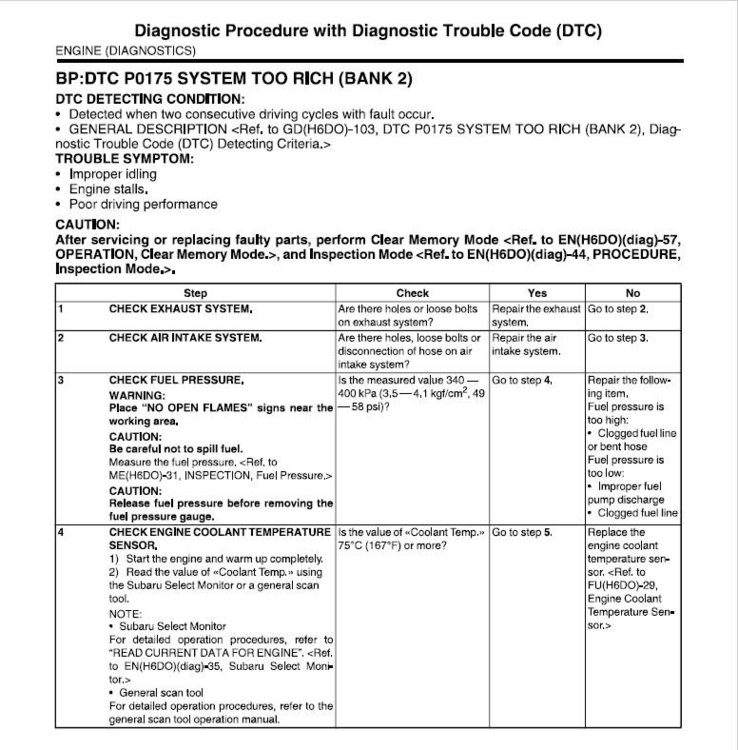
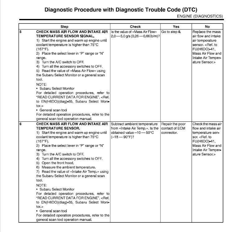
I found this in the FSM. Hope it helps. It shows 6 things to check that can cause misfires on all 6 cylinders.
- 19 replies
-
- 2012 outback
- misfire
-
(and 1 more)
Tagged with:
-
I use this for cleaning a lot of stuff, even paint overspray from my fingers. I buy it by the case. If the fuel pump quits, have someone spray it into the intake and you can drive the car into the garage. BERKEBILE 2+2® Instant Gum Cutter Cleans Automatic Chokes, Carburetors, Choke Linkages, and PCV Valves & Hoses! Removes Varnish, Gum, & other Deposits Instantly!
-
I throw it in the box of spare parts. On our 95 and 97 RHD 2.2s they are hard as a rock and the tab that holds it in place breaks off. I can remember when they were pliable and would snap into place. Our 95 has 472k miles on it and that cover has been off since around 120k. I wouldn't bother. If you want to go through the trouble, then use Permatex Hi tack in the can with a brush on the lid. It won't leak and it takes forever to get hard.
-
Looks like you found the culprit. Some of the wires will be broken (headlights) and some shorted (wipers). If you repair it, use heat shrink crimp connectors to seal the connection. To replace the harness would be quite a chore, but it can be done. The front harness goes in under the dash. Front Harness.pdf
-
Ea82 ignition switches short
Rampage replied to Olyroller83GL's topic in Old Gen.: 80's GL/DL/XT/Loyales...
Is the melting happening right at the switch? If so, then the contacts inside the switch are dirty and not making full contact and getting hot. Are you replacing the switch with used ones? If so, then same problem. Is the alternator charging at 13.8 volts or way higher? -
Almost. When I replaced the timing kit on our 95 RHD EJ22 a few years ago, while torqueing the pully bolts I noticed the bolt on the lower smooth pully did not tighten up, so I quit turning it. There is very little pressure on that pully so I let it as is and it is still ok. Next time I will have to use a helicoil.
-
As Numbchux said, plug in a scanner bring up live data, select engine temp, and go for a ride. See what the ECU says the temp is. If it is around 203 F. then the ECU will turn the fan on. To find out if "both" fans are capable of low and high speed do the following. Under the steering wheel are two green connectors. Connect them but do not make it click, they are hard to separate once they latch. Turn the Ignition Switch Key to on. Do not start. After the fuel pump and some solenoids and relays click, Both fans should run together on low speed, then both on high speed. Let it cycle a few times then turn the key off and unplug the green connectors. That will prove if the relays and fan motors are working like they should. If both fans do not run low and high together, then one of the motors or a relay is bad. Next to find out if you have one of the few that only runs one fan on low, I would check pins 73 and 74 on the ECU. If the ECU is not calling for cooling both pins will be at high voltage (battery voltage). On MOST models pin 74 goes low first to run both fans on low speed. If pin 73 goes low first then only one fan will run. If the engine gets hotter or the A/C is turned on both pins 73 and 74 will go low and both fans will run at high speed.


