Rampage
Members-
Posts
683 -
Joined
-
Last visited
-
Days Won
25
Content Type
Profiles
Forums
Gallery
Store
Everything posted by Rampage
-
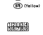
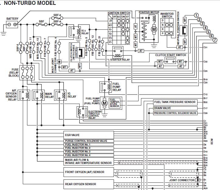
SBF2 is open, or a wire to or from it. If you grounded pins 2 or 3, I have no idea if it would have damaged the Engine Control Module or not. If you grounded pin 5 then when you turned the key on the Main Relay would have closed its contacts. The only fuse to the battery is SBF2. Yellow connector. See image below. Pin-Goes to 2---ECM 3---ECM 5---Main Relay contact (other contact goes to SBF2 30amp) 9---Ground Slow Blow Fuse 2 is located in the fuse box under the hood. SBF2 30amp powers the following. ECM Fuel pump relay Main relay OBD-2 service connector
-
My wife is a Rural Carrier for the Post Office and the 95 and 97 are Right Hand Drive Legacy wagons AWD with EJ22 and automatic. If the tranny oil does not smell burnt, just do a drain and fill. Found this on Valvoline's web site. Is it OK to mix synthetic ATF with a conventional and/or synthetic blend ATF? Yes. Synthetic ATF and conventional fluids are 100 percent compatible with each other. I never expected that, but I trust Valvoline. In the early 70's I read an article that said they had the best 20-50 Racing Motor Oil on the market. Within 5 tests all other racing oils broke down, it took 2 more tests to get the Valvoline to start to break down.
-
This is one thing to check. The Main Relay contacts might be starting to burn and fail. Usually they last a very long time. See image below. The Mass Air Flow sensor, EGR valve and Injectors get their supply voltage from the Main Relay. Check the voltage and see how in compares to battery voltage. On the MAF and Injectors the wire color is Yellow with a green stripe. You might have to hook up a wire and bring it inside so you can watch the voltage as you drive. Battery is 12 volt, but with the engine running the alternator increases the voltage. Replacing the Main Relay might be easier.
-
The Factory Service Manual recommends changing transmission fluid by using the drain plug and to replace the amount taken out. Then check it idling and hot. Put in a little less than you drained out and start it. Check and add as it warms up. Get a white paper towel and put a drop of fresh ATF on it then pull the dipstick and put that beside it and compare look and smell. Keep in mind, if they put a Full Synthetic in it, it will smell way different than regular ATF. If your transmission, torque converter and cooling lines are completely empty it, would take 9.2 to 10.1 quarts depending on the engine size. On our 95 and 97 4EAT, if I drop the pan and remove the pipe that runs under the filter, I put almost 8 quarts back in it, and it is supposed to hold 8.4.
-
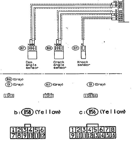
That will work, but you will run into the shield around the two signal wires. In the picture above the dotted lines are the shield around the signal wires. All you can do is experiment. Gently cut the outer insulation and see what you have to work with. The exposed wires you splice in must be as short as possible because they will pick up noise from ignition wires and other things. You could splice in an extra wire with the shield wire crimp on each of the new connectors and then when you're done splicing and have it taped wrap it with aluminum foil and strip that extra wire and lay it on the foil and wrap it one or two more times then tape over it. That will work good as a shield.
-
Now to find out which wire or the plug. Repairing the break depends on where it is and how much wire you have to work with. Soldering is ok, but it will melt the insulation on the wire. What I do is use a heat sink on the wire to protect the insulation. A pair of needle nose plyers works good. I have several spring loaded aluminum clips that work like a cloths pin. They are from my electronics days. Normally I poke the stripped end of the wire into silicon grease and use crimp connectors. This might be useful, they make a liquid tape that is applied with a brush on the lid. Even hardware stores carry it around here.
-
On the wire from the harness of the car to the sensor connector one of the outside pins is the shield and ground (on a 92 it is yellow) and the other two are signal (black and white). I checked rock-auto and 91 and 92 use the same sensor. The colors on the sensor plug could differ. Sure does...or a loose or corroded or broken pin.
-
As GD said, inductive. It basically works like a coil reacting to a magnet. The output will be a sinewave, the frequency of it will increase with rpms. When doing a timing belt, if you look at the timing mark on the crankshaft you will see multiple tabs sticking out of that ring with different spacing. This is how the ECU knows when number 1 cylinder is top dead center and when to fire that plug and each one after that. Pull the sensor out and see if there is any crud built up on the end of it. Most service manuals recommend NOT probing certain wires going into the ECU with an ohm meter because the output voltage of an ohm meter may be high enough to damage the ECU. You should unplug the ECU connector and probe from the pin of the connector to the plug you are working with. You can however unplug the connector from the sensor and probe the sensor for ohms. You mentioned it acting worse after plugging it back in. Did you probe the wires with the ohm meter? It could be as simple as a partially broken wire near the plug, or dirty contacts. Between that connector and the ECU the wires are shielded like in a coax cable.
-
Try this tool to locate the noise. Some times I use my 18 inch screwdriver but you can use a 1/2 dowel rod sharpened somewhat to a point on one end. Hold the other end of it in your hand like making a fist and put your first finger and thumb against your ear. Touch the other end on different places and listen to the noise. First try it on the alternator front and back. Then put it on the bolt of an idler pully. If the noise is a lifter you can move the stick along the edge of the head or on the bolts of the valve cover. Somewhere the noise should be louder.
-
The front axle joints have a slight tendency to push outward on the wheels as they rotate because they are angled forward to the wheels. Take a look at the control arm bushings. It's hard to judge the front one by looking at it, but the rear bushing has a big washer. If that washer does not look centered on the bracket the rubber is bad and will allow movement in the control arm. I have replaced both of them on both of our cars.
-
I thought you would have. You probably spun the wheels when you had the front jacked up to see if they spin true. Take the car out again and this time turn the steering wheel about a quarter turn to the right and let it roll then the same to the left. See if the wobble is weaker or stronger. If it is then it is an axle binding. Turning the wheel to the right will allow the left spindle line up with the axle and have less pressure on the cv joint and vice-versa.
-
Well, I was expecting more movement. It happened on our 95 after I installed a new aftermarket axle (my last new one) and the steering wheel would turn a quarter turn to the right. It was the new axle. The outer joint was way too tight. Earlier you said you were cleaning the hubs. Did you clean the inside of the rotors that mate with the hubs? A chunk of rust between the two will cause a wobble in the wheel.
-
Yes, it is too high. A 12 volt lead acid battery should be charged at 14 volts. Any higher and it will eat away the lead plates and boils away the acid. That higher charge voltage is the main reason you see so many newer vehicles with burned out headlights and parking lights. The older cars like our 95 charge at 13.8 volts. I very seldom have a burned out bulb. I think two parking lights in the last ten years. Never a headlight. Usually it is just a corroded connection from moisture and age or heat.
- 12 replies
-
- 1
-

-
- battery light
- brake light
-
(and 1 more)
Tagged with:
-
Imdew is right, there is no factory adjustment for Camber on the rear. Camber is how much the tire tilts in or out at the top. 1 Lucky Texan is right on. Tires will wear on the inside if they are Toed out too much. The manual calls for a slight toe-in on the rear tires. Front tires are 0 toe-in. You might want to check Toe-in on the rear tires. This is not perfect, but it will give you an idea if the Toe is way out or not. Get someone to help. Use a wide tape measure and check the front and rear of the rear tires. Hook the end of the tape in the outer most groove of the tread of the left tire and read the measurement to the outer most groove on the right tire. Since this Forrester does have a Toe-in you will have to do both measurements at the same height form the ground. Keep the tape taught and as straight as possible. Compare the two measurements. From the FSM. 2±3 mm (0.08±0.12 in) When performing toe-in adjustment, align to 2 mm (0.08 in) as near as possible. (I think they are talking per side here but not sure). Also this would be at center line with the axle and you are measuring below that, so your measurement should show a little less Toe-in. If your measurements show a Toe-out, then check all the rubber bushings in the 2 Lateral Links and the Trailing Arm on each side. Compare side to side. Look for cracks in the rubber bushings. The inner bolt on both left and right Rear Lateral Links is used for adjusting Toe-in, so they may look off center. Changing those parts can be a real pain.
-
Earlier cars charged at 13.8 V. Some of the newer ones are around 14.4 V. I have a Remy alternator right now that I have to return because it put out too much voltage. It melted the plastic on the coil for the clutch on the A/C Compressor among other things. After I saw that plastic slung all over the place, I did not want to start it just to see what the voltage really was. Subaru's price for the A/C Compressor on our 95 RHD Legacy Wagon is around $1000.00. I looked at a WRX two years ago for a friend that was blowing an 80 AMP fuse. The alternator was putting out over 20 Volts and it was the original that came on the car.
- 12 replies
-
- 1
-

-
- battery light
- brake light
-
(and 1 more)
Tagged with:
-
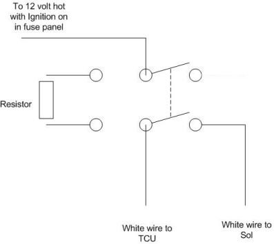
You will need a Double Pole - Double Throw switch (amps don't matter) and a 560-600 ohm resistor 1/2 watt. The terminals on the switch are laid our like the circles in the diagram. Hook up the resistor and wires like in the diagram. In the diagram the switch is horizontal. You will probably want to mount it vertical so the toggle moves up and down. Put the end with the resistor up. That way when the toggle is down the solenoid will not operate. You can get access to the white-b wire under the dash on the plug B55 pin 3 on the TCU. Make sure that Pin 3 is White-b. Sometimes the color listed may be wrong. It was wrong on my 96 Voyager when I rewired the headlight switch to bypass the BCM. Make sure you hook up the two ends correctly. One goes to the TCU and the other goes to the Solenoid.
-
Theoretically yes. But if the TCU is built like the ECU it will detect an open circuit to the coil of the solenoid and throw a code. You will have to add a 600 ohm resistor to fool the TCU. I will draw a circuit for you and post it later. The lock-up solenoid is for the torque converter lock-up after the vehicle gets above a certain speed in high gear.


